
Sphero Block direct attachment for implants

The Sphero Block direct attachment for implants logo

Direct attachment for implants

Sphero Block

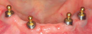
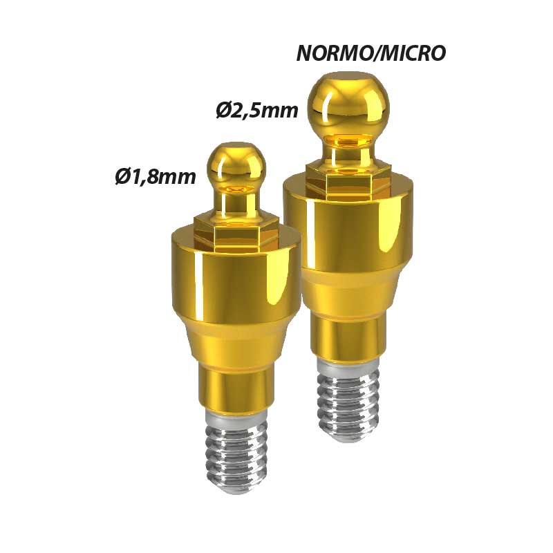
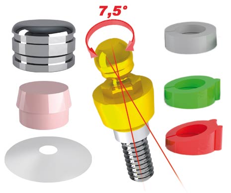
The Sphero Block direct attachment for implants is made of titanium with nitride coating and is available for any implant brand currently on the market in 2.5 mm (Normo) and 1.8 mm (Micro) spherical diameters. The nitride coating is a treatment that gives a surface hardness of 1600 Vickers.

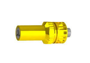
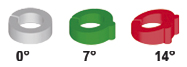
Thanks to the use of directional rings, this attachment corrects disparallelisms of up to 14° for each implant. The functioning of this attachment is guaranteed by the coupling between the sphere and the retention cap inside the metal housing. Retention caps are available in different colours corresponding to the different retention levels.
PRODUCT INFO

DENTAL CLINIC

LABORATORY

PRODUCT SPECIFICATIONS

VIDEO

PRODUCT INFO

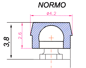
SPHERO BLOCK NORMO Ref. 002

SPHERO BLOCK NORMO

Ref. 002

Kit contains:

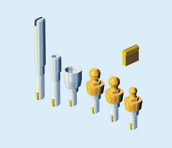
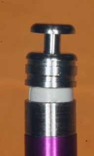
• 1 TITANIUM ABUTMENT (2.5mm sphere)
3 CAPS (Yellow - Pink - Clear)
• 1 STAINLESS STEEL HOUSING
• 1 PROTECTIVE DISK
• 3 DIRECTIONAL RINGS


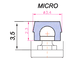
SPHERO BLOCK Micro Ref. 003

SPHERO BLOCK MICRO

Ref. 003

Kit contains:

• 1 TITANIUM ABUTMENT (1.8 mm sphere)
• 3 CAPS (Yellow - Pink - Clear)
• 1 STAINLESS STEEL HOUSING
• 1 PROTECTIVE DISK
• 3 DIRECTIONAL RINGS


DIRECTIONAL RINGS FOR SPHERO FLEX AND BLOCK

DIRECTIONAL RINGS FOR SPHERO FLEX AND BLOCK

Ref. 100AD

Kit contains:

• 3 COLOURED RINGS (with inclination of 0° - 7° - 14°)


AUXILIARY TOOLS


Chiave Sphero block flex oro 771CEF chiusa

Ref. 771CEF

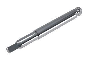
• 1 KEY FOR SPHERO FLEX AND SPHERO BLOCK (Normal - Micro size) HEX 2.3mm


Chiave manipolo equator da-sola 760CE

Ref. 760CBM

• 1 HEX SCREWDRIVER FOR TORQUE CONTROLLER CONTRA ANGLE HEX 1.3mm


Ref. TE

• ANTI-UNSCREWING SYSTEM WITH AN ELASTIC DOWEL

APPLICABLE TO SPHERO FLEX-BLOCK - OT REVERSE AND DIFFERENT SCREWS. THE ELASTIC DOWEL IS APPLICABLE ONLY UPON REQUEST TO ALL SCREWS WITH A NOT INFERIOR M. 1.8 to screws - Sphero Flex - Sphero Block - OT Reverse attachments, etc.


DENTAL CLINIC

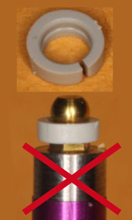
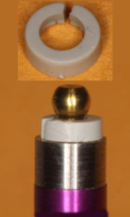
Directional rings correct placement

Before placing the impression abutment on the implant it is suggested to put a gray directional ring (for parallel systems) or a ring for angled implants if not parallel.

This will keep the impression coping “on level” during the impression. The directional rings have only one direction of insertion.

Wrong placement

Correct placement

Chairside procedure for positioning the caps

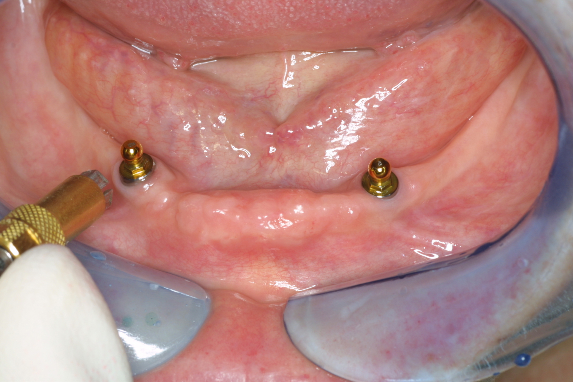
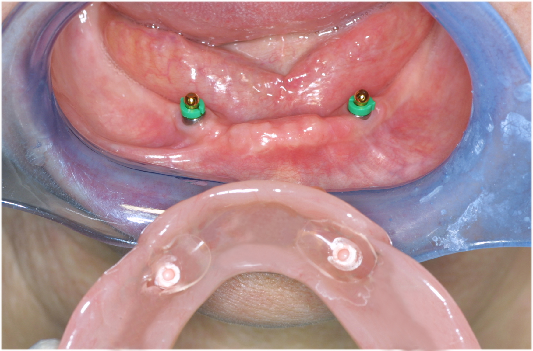
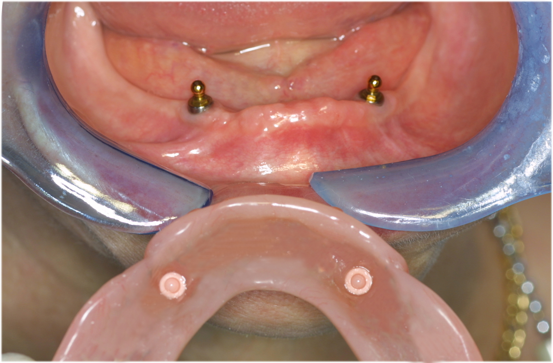
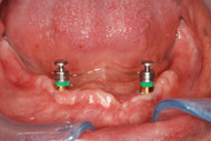
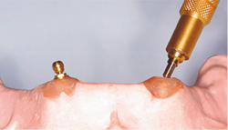
Screw the abutment into the implant. For best results, unscrew and screw the abutment 3/4 times and then tight firmly.

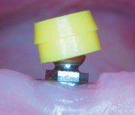
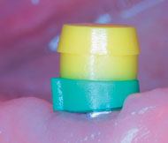
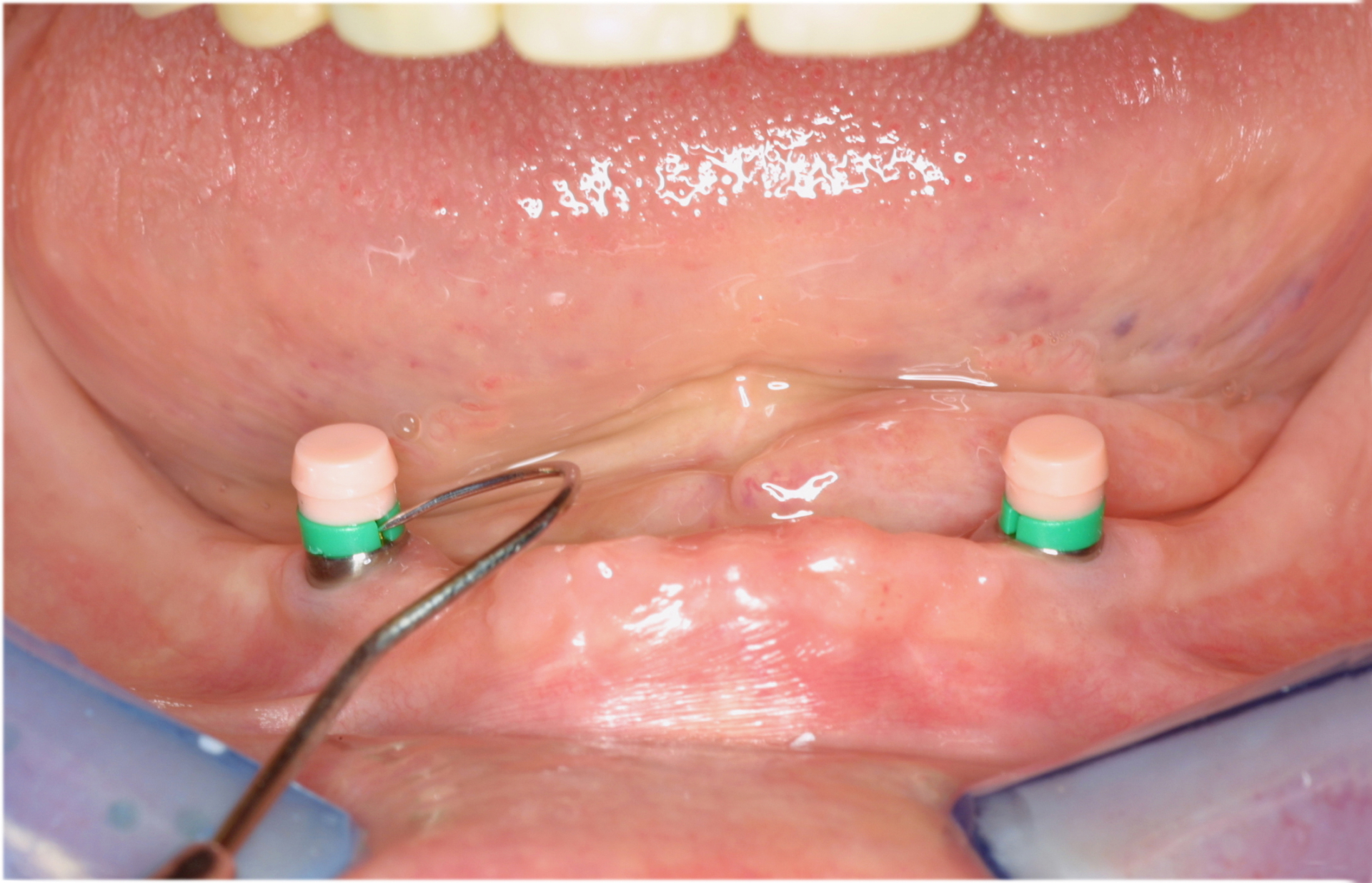
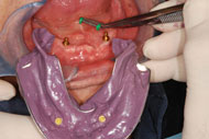
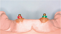
Select the appropriate directional rings and place them over the spheres. Be sure that the ring is aligned with the hex and seated properly on the platform.

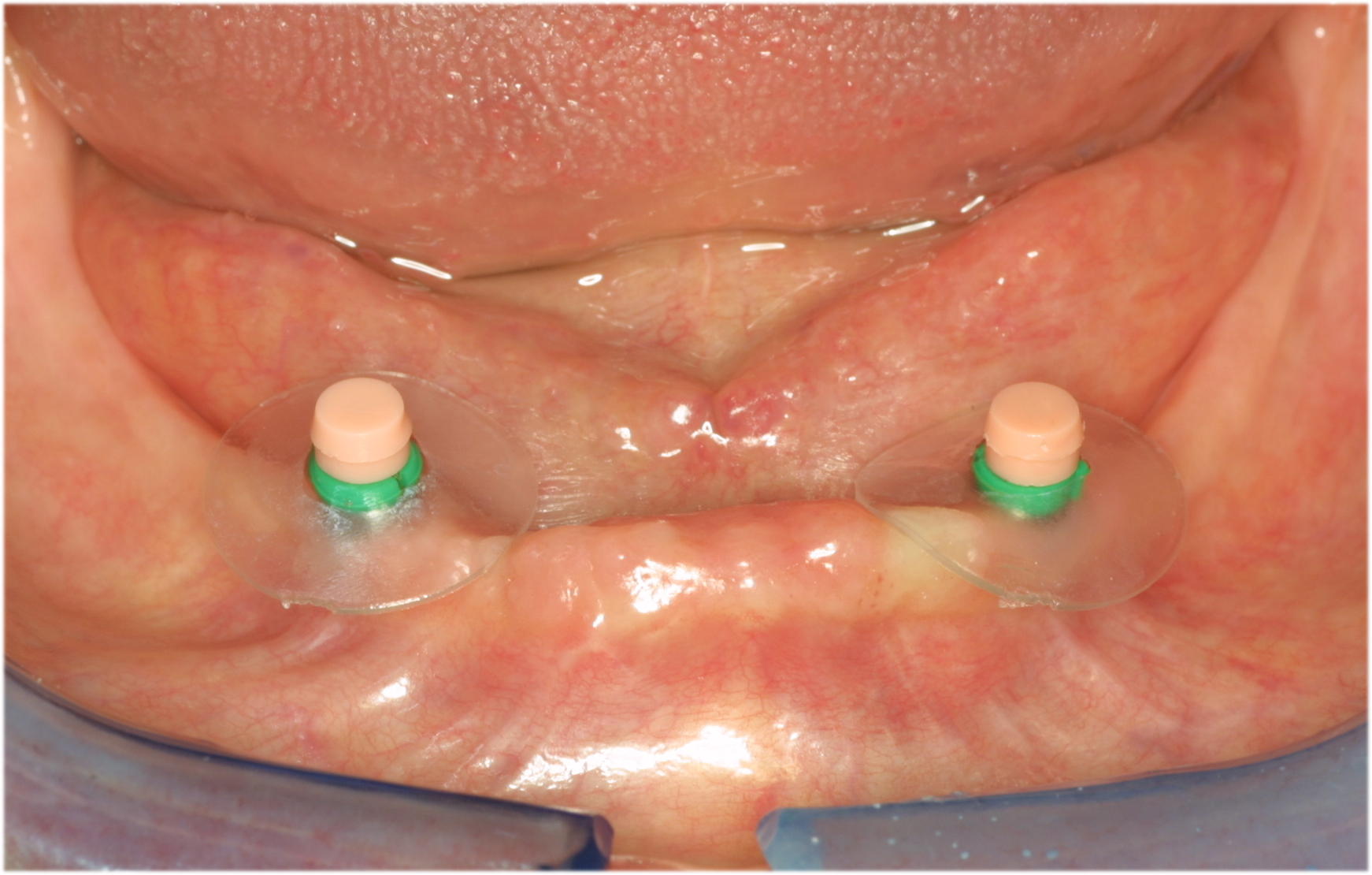
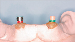
Once the directional rings have been positioned, it is advisable to remove the retentive caps and place a protective disk over the spheres. Replace the retentive caps in original position when finished.

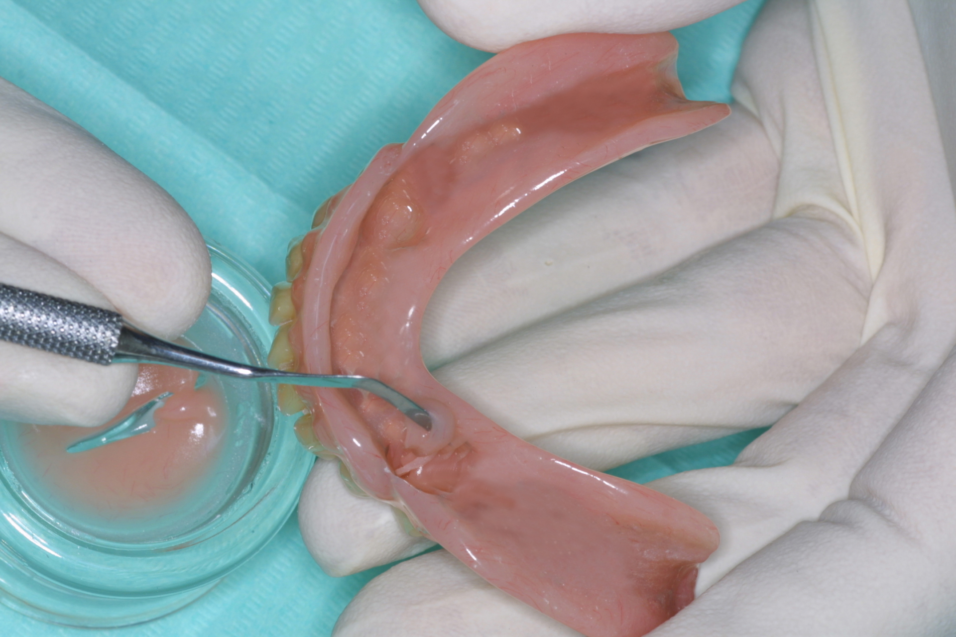
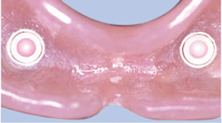
Try the prosthesis in the mouth. Check to see if there is enough space for the retentive caps. Fill the holes with self-curing resin and position the prosthesis over the caps and
spheres in the patient’s mouth.

Once the resin has hardened, remove the prosthesis. Remove the protective disk along with any excess resin.

Prosthesis finished.

Taking impression transfer

Place the directional ring over the sphere with the flat side facing down. Place the impression coping over the sphere.

Rotate the directional rings to achieve a common axis parallel to the occlusal plane and take the impression.

Remove impression. Directional rings must be removed from the impression and spheres.

Place the analogs into the impression copings and send to the laboratory for model fabrication.

LABORATORY

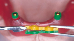
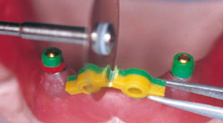
Directional rings (green) on the base of the abutment. Green OT BOX position ring inserted on top. OT BOX bars glued on.Cut off the excess OT BOX bar, only one part of the container is used for the retention cap.

Ot Box Classic NORMAL - Cast reinforced acrylic prosthesis using directional rings

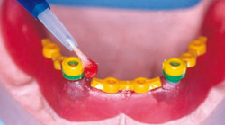
Place directional rings over the spheres. OT BOX is placed over the directional rings, ensuring that the horizontal plane is level. Connect with resin.

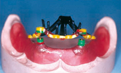
The constructed OT BOX substructure with reinforced wax pins. Sprued and ready for casting.

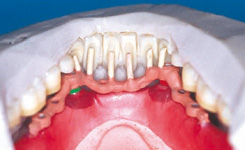
The cast substructure on the model. The metal reinforcement pins for each tooth are positioned according to the silicone mask.

Finished prosthesis with caps inserted in the cast OT BOX housings.

Resin-only prosthesis construction with directional rings

Screw the abutment on the model and choose the appropriate cuff height.

Mount the directional rings and rotate them until you find the position that will achieve optimal parallelism

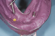
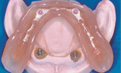
Because of the elasticity of the retentive caps, they work very well if incorporated in the acrylic and/or in the pre-fabricated stainless steel housing. By using the stainless steel housing it is much easier to change the retentive caps.

The finished prosthesis with the stainless steel housing and retentive caps in place.

PRODUCT SPECIFICATIONS